
Ebike Controller Wiring Diagram
E Bike Schematic Diagrams are simple graphical representations of the wiring and electrical connections between the various components of an electric bike. These diagrams are essential tools when troubleshooting any type of electric bike, as they give a visual breakdown of how the wiring is configured and connected.

Wiring Diagram Electric Bike Controller
Understanding the electric bike dual motor controller schematic is essential for anyone who wants to ensure the efficient operation of their electric bicycle. By understanding the different components of the scheme and how each of them works together, you can ensure that your electric bike runs smoothly and safely. S06p S Ku63 Controller.
Electric Bike Controller Wiring Diagram Wiring Diagram
1. Get the right tools and materials. You'll need a soldering iron, wire strippers, electrical tape, and a variety of crimp connectors. 2. Gather all the components of the e-bike controller. Make sure you have everything needed to assemble the controller. 3. Create a schematic diagram.

Electric Bike Motor Controller Schematic
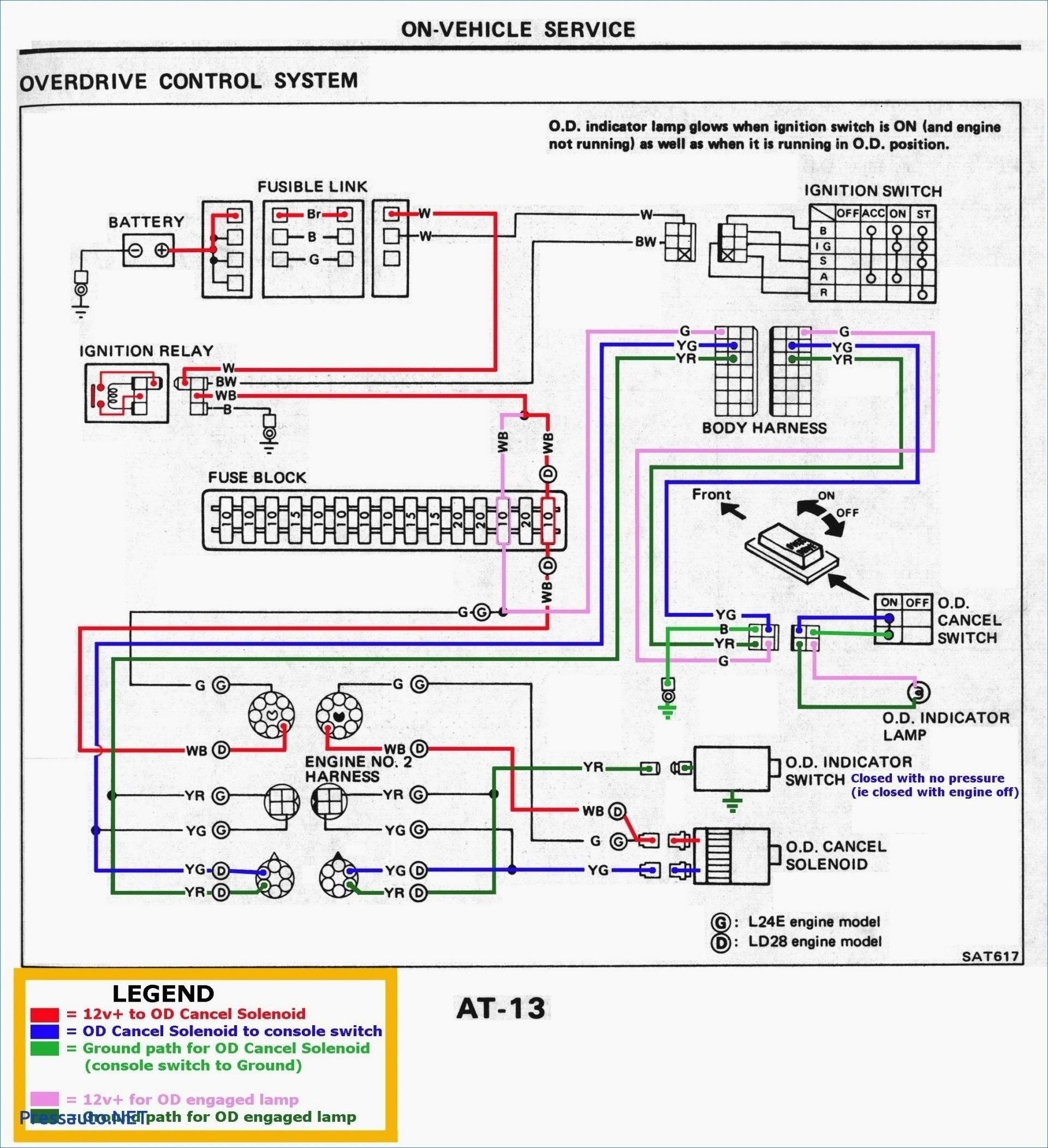
The diagram should always be read from left to right, with each component being labeled and connected to the next component in the chain. This will help you identify which parts need to be connected, and in what order. Identifying Connectors in an Electric Bike Controller Wiring Diagram
24v Electric Bike Controller Wiring Diagram
Strip the ends of the wires to expose the conductive copper, and crimp or solder connectors to the stripped ends. This will help ensure secure and reliable connections. Connect the battery The first step in wiring your ebike controller is to connect the battery.

Electric Bike Controller Wiring Diagram Wiring Diagram and Schematics
Common Wiring Format for E Bike Controllers. The diagram below illustrates the general wiring format for connecting an ebike controller to your bike's motor, battery and other components. This diagram may vary based on the type of controller and bike, but the basic rules still apply regardless of the brand or model.

48V Ebike Controller Wiring Diagram Wiring Diagram Schematic
The 24v Electric Bike Controller Wiring Diagram is an essential part of any electric bike system. This diagram shows the wiring connections necessary to make sure that the electric bike is safe and works optimally. The diagram contains several components including an electric bike controller, battery, and motor.
Schaltplan E Bike Controller Wiring Diagram
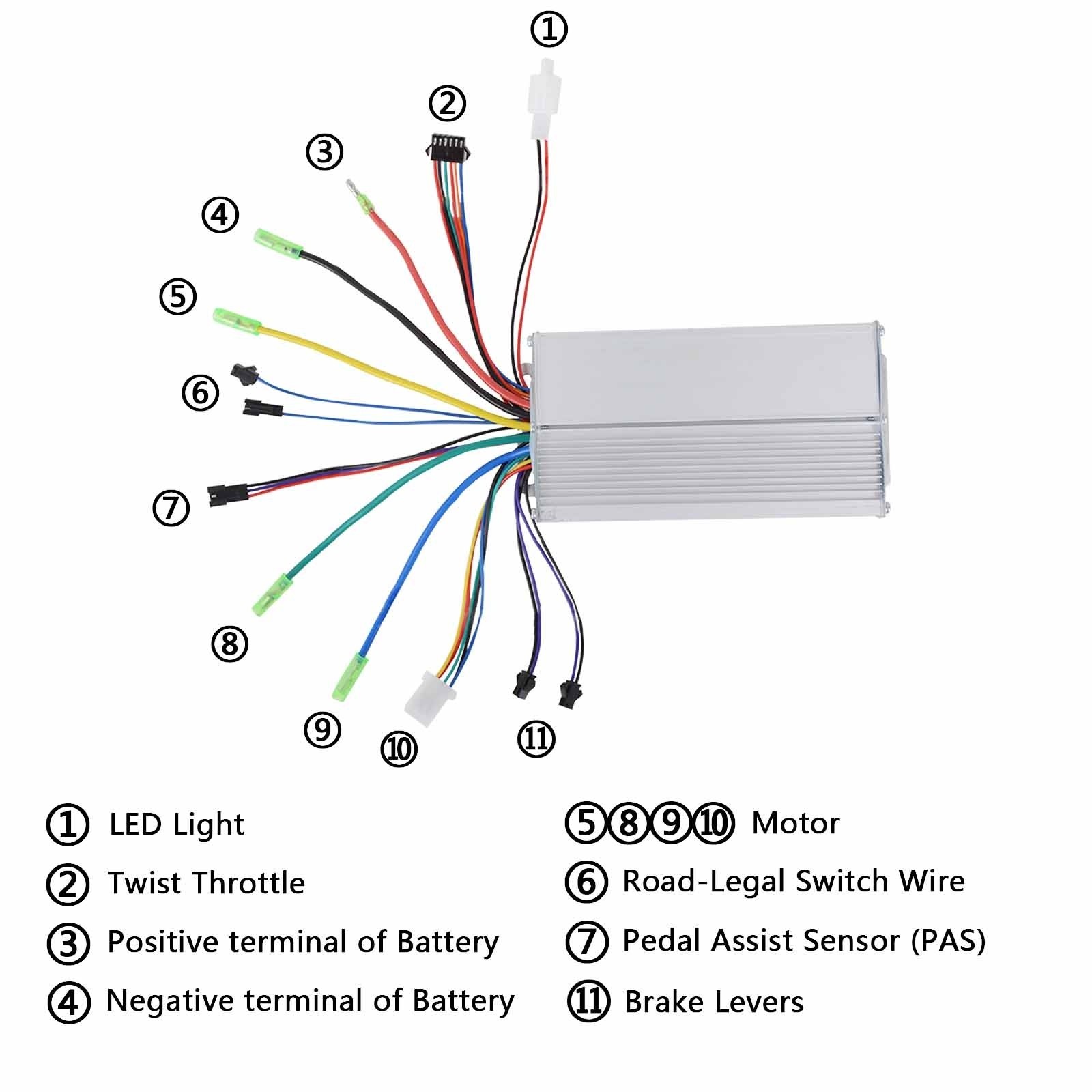
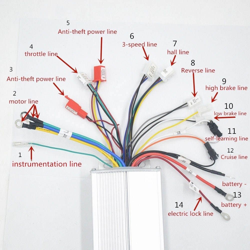
The main wires include the power wires, throttle wires, motor wires, brake wires, and display wires. Each wire has a specific purpose, such as delivering power to the motor, receiving input from the throttle, regulating the brakes, and displaying information on the control panel.

36 Volt E Bike Controller Wiring Diagram
The core function of an electric bike controller is to take all the inputs from all the electric components ( throttle, speed sensor, display, battery, motor, etc.) and then determine what should be signaled in return to them (motor, battery, display).

Schematic E Bike Controller Wiring Diagram
An electric bike wiring diagram is a schematic representation of the electrical connections of an electric bike. It typically consists of a number of symbols that are connected by lines to indicate the various circuits and connections between the components.
E Scooter Controller Wiring Diagram
First it starts out a schematic: Here is the schematic of how the front connectors fork out from one connection coming from controller: According to Tora, owner of Juiced Riders who is one of the few ebike manufacturers who is open about the way he sources in China:

Electric Bike Controller Wiring Diagram
A wiring diagram for the e-bike controller is essential to ensure that all the components are connected correctly and that the bike runs safely and efficiently. A wiring diagram for an e-bike controller consists of a visual representation of the various components that make up the circuit, including the battery, motor, controller, and other.

️E Bike Controller Wiring Diagram Free Download Gambr.co
The diagram will show the various components of the system and how they are connected. The diagram will also show the various inputs and outputs that the system has, as well as the power sources for the system. It will also show the various safety features that are built into the system.
Circuit Diagram Of Electric Bike Controller Switch Wiring Diagram
1. Ensure You Have The Power Connectors Set Up Properly The power connector has 3 wires; the two large wires are the positive (red) and negative (black) wires. The smaller wire is a switch that turns on the circuit when connected to the positive and shuts down the circuit when connected to the negative.

Ebike Electric Scooter Wiring Diagram
The Step Through was for my wife's ease of use. Problem is that the bikes are now 3+ MPH different with identical settings so it's impossible to ride together without one of us just using PAS 0 which kinda defeats the whole purpose of getting e-bikes. Lectric said I can take the controller from one of the XPs and transplant it into the Step.

48v Ebike Wiring Diagram
Patreon - https://www.patreon.com/evcustomsChannel Support - https://www.paypal.com/paypalme/evcustoms?locale.x=en_USEV-Customs Website - http://ev-customs.c.
